THE SEA SOLAR ENERGY CONVERSION SYSTEM
SEA SOLAR ENERGY CONVERSION SYSTEMS have multiple rows of parabolic trough reflectors that focus sunlight onto actively cooled arrays of solar cells. Sun tracking is accomplished by rotating the entire system in a horizontal plane about a central vertical axis. As SEA systems track the sun, the optical planes of the reflectors remain vertical. They don’t tilt or roll as in existing parabolic trough reflector systems, so they don’t produce mutual shadowing at low sun angles. This means that they can be placed side by side, collecting sunlight from more than 95% of the area covered by the reflector field. That’s important because solar energy conversion systems must ultimately be located near the energy markets they serve, utilizing the solar resource locally, rather than in remote desert regions where land costs are minimal.
SEA systems collect sunlight from more than 95% of the area covered by the reflector field, allowing them to be economically located near the energy markets they serve.
When irradiated by the intense sunlight (25 to 30 suns) coming from an SEA system’s reflectors, the solar cells (back-contact, single-crystal silicon solar cells) produce electrical energy with an efficiency approaching 25%. Active cooling of the cells maintains their high efficiency even when the cells are exposed to this high intensity sunlight. Also, the light-concentrating power of the parabolic trough reflectors reduces—by a factor of 25 to 30—the area, and thus the cost, of the solar cells required to generate a given amount of electrical power.
SEA systems reduce by a factor of 25 to 30 the area, and the thus cost, of the solar cells required to generate a given amount of electrical power. This eliminates a major cost driver for solar-cell-based systems.
In addition to generating electricity, SEA systems produce large quantities of valuable low-grade thermal energy. Coolant flowing through cooling channels that support the solar cell arrays collects the thermal energy (heat) that is produced within the irradiated cells. This thermal energy, which amounts to roughly 75% of incident solar radiation, is normally discarded as waste heat, but our systems collect it, store it, and make it available for later use. Another important feature of SEA systems is that the technology used during summer months to store thermal energy for heating during the winter can also be used in reverse during the winter to provide a cold in-ground reservoir for air conditioning during the summer, and air conditioning is one of the biggest electricity-use categories in our homes and businesses.
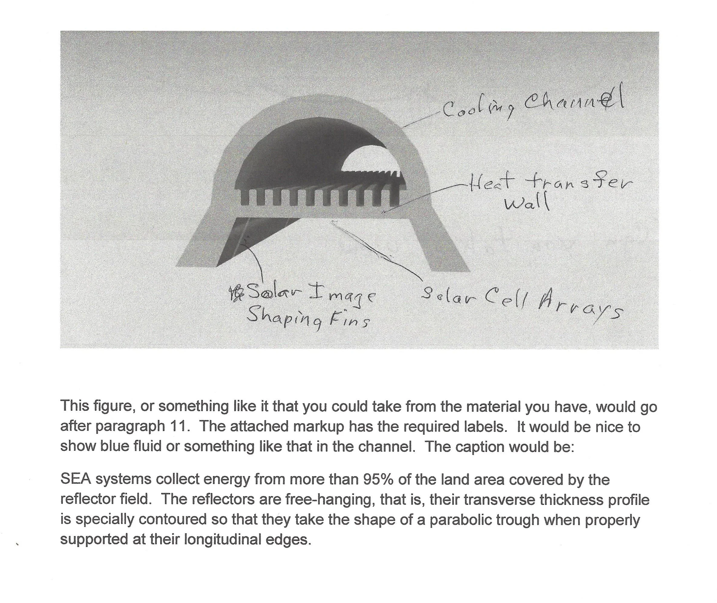
The solar cells in SEA systems are mounted to cooling channels which remove thermal energy (heat) from irradiated cells and collect that energy in a liquid coolant.
Overall, SEA systems convert nearly 90% of incident solar radiation into useful output. That’s a pretty remarkable number, but of even greater importance is the fact that our systems can easily incorporate proven technologies that provide long-term (seasonal) storage of both the electrical and the low-grade thermal energy that is produced.
Regarding storage of the low-grade thermal energy provided by our systems, heated coolant exiting the cooling channels can be circulated through borehole heat exchangers, where thermal energy in the coolant is transferred to underground thermal storage reservoirs (undisturbed layers of soil, gravel, and rock). This energy can be reclaimed as needed—after days, weeks or even months of storage—for space heating and hot water heating of homes and businesses, or for process heat for industrial or agricultural operations. This proven technology is referred to as Borehole Seasonal Thermal Energy Storage (BSTES) and it is now being used successfully in a number of locations in northern Europe and Canada, e.g. www.braedstrupfjernvarm.dk or www.dlsc.ca. The BSTES technology utilized in these systems is extremely efficient, with coefficient of performance (COP) values of 30 being typical. That’s equivalent to a Seasonal Energy Efficiency Ratio (SEER) of 120.


2016 Residential Energy and Electricity Use (Source: US EIA)
More than 75% of domestic energy use, and nearly 40% of domestic electricity use, is for low temperature (35F to 85F) applications that include space heating, portable heaters, space cooling, cloths drying, and hot water heating. A large part of this energy can be supplied from low temperature energy storage reservoirs and thermal energy transfer systems working in conjunction with SEA solar energy conversion systems.
Regarding the electricity produced by our systems, some will be used as it is produced, some will be stored in batteries for the short term (overnight or for a few days), and the majority will be stored for the long term (season-to-season) in the form of fuel. The fuel produced can be stored until needed and then burned in a heat engine to regenerate a portion of the electricity that was originally used to create the fuel, or the fuel can be used to perform other tasks, such as powering transportation vehicles. In the past, processes that involved electrolysis, a fuel, and a heat engine (electrolysis-storage-reconversion or ESR cycles) could not be considered viable energy storage technologies, primarily because of inefficiencies that were inherent in heat engines. Now, at SEA, we have designed and will soon begin development of a high-efficiency, two-stroke internal combustion engine which will make ESR cycles efficient and cost-effective energy storage mechanisms.
SEA has patented a high-efficiency two-stroke internal combustion engine which makes Electrolysis-Storage-Reconversion (ESR) cycles economically viable options for long term storage of electrical energy.
HOW OUR SOLAR ENERGY CONVERSION SYSTEM WORKS
Parabolic trough reflector systems track the sun by continuously changing the orientation of the reflectors in one angular dimension. The technique used for sun tracking in SEA systems is different from the sun tracking in other parabolic trough reflector systems, and that difference gives SEA systems a design flexibility that leads to several important structural and performance advantages. To understand why sun tracking techniques are so important, let’s look first at existing parabolic trough reflector systems.
All currently operating parabolic trough reflector systems, thermal and solar-cell-based, have reflectors whose longitudinal axes are permanently aligned in a fixed direction, usually in either a north–south direction or an east–west direction. In these systems, each reflector tilts (rolls) about an axis parallel to its focal line as it tracks the sun. Systems with this type of sun tracking are referred to as Tilting Trough Reflector (TTR) systems. TTR systems are by far the most common type of CSP system currently in use, but they have three serious problems.
The first problem with TTR systems is that, since the reflectors tilt in order to track the sun, the individual rows of reflectors must be separated in order to avoid mutual shadowing at low sun angles. This leads to poor land area utilization, which is on the order of 30% in most TTR systems. (The situation is even worse for Central Tower systems because the reflectors must track in two angular dimensions, rather than just one, and land area usage within the reflector field is often less than 20%.) Poor land area utilization means that TTR systems can only be deployed in areas where average daily insolation is high and land costs are low. Such locations are usually far from the population and industrial centers that use the energy. Since low grade thermal energy cannot be economically transported over long distances, the poor land area utilization exhibited by TTR systems prevents them from being used as cogeneration (electricity and thermal energy) systems.

The reflectors in TTR Systems require substantial mechanical support structure to withstand the deformation stresses developed as they tilt to track the sun.
The second problem with TTR systems is that, during sun-tracking operations, the parabolic trough reflectors are subjected to directionally-varying forces. Reflector support structures are thereby exposed to severe bending and torsional stresses. Both the reflectors and the support hardware must be designed to function effectively in spite of these challenging mechanical requirements. This significantly increases TTR system cost, decreases system reliability, and seriously limits available options for system optical design.

Tilting Trough Reflector (TTR) systems collect sunlight from less than 30% of the land area occupied by the reflector field
The third problem with TTR systems is that, since the parabolic trough reflectors are permanently oriented in a fixed direction, they are exposed to severe wind-induced stresses whenever strong winds blow crosswise to the direction of their longitudinal axes. This places additional mechanical demands on both the reflectors and the support structure, again adding to hardware manufacturing costs and system complexity, while at the same time decreasing system reliability.
SEA solar energy conversion systems use parabolic trough reflectors, but they track the sun in a way that avoids the inherent problems associated with TTR systems. In SEA systems, the rows of parabolic trough reflectors do not have a fixed north-south or east-west orientation. Instead, sun tracking is accomplished by rotating all the rows of reflectors and the associated rows of receiver elements as a single interconnected unit, with the rotation of the unit occurring in a horizontal plane about a central vertical axis. The individual reflectors do not tilt as they track the sun and the optical plane of each reflector is always held in a fixed vertical orientation. Since the reflectors do not tilt, they can be positioned side by side, thus providing efficient utilization of available land area. This solves the first problem mentioned above. SEA systems collect energy from more than 95% of the land area covered by the reflector field.
As SEA systems track the sun, the reflectors and the elements of the associated support fixtures are exposed to gravitational loads that are invariant in both magnitude and direction. This characteristic is very important because the design of the reflectors and the support hardware can be greatly simplified—and their fabrication and installation costs can be significantly reduced. SEA has patented a free-hanging (support structure needed only at the reflector edges) parabolic trough reflector that can only be used in SEA-type solar energy conversion systems that have gravitational forces acting parallel to the optical planes of the reflectors. These reflectors provide high optical quality, simple manufacturing processes, and minimal associated support structure. Our free-hanging reflector approach solves the second problem mentioned above.
Another advantage of the SEA system is that, since the orientation of the rows of reflectors is not fixed in one specific direction, sun tracking for our systems may be temporarily interrupted whenever wind velocities reach a high level. The reflectors can then be reoriented so their longitudinal axes are aligned with wind direction. This feature greatly reduces the likelihood that wind-induced stresses could cause physical damage to the system. This solves the third problem mentioned above.
Since the reflectors in SEA systems don’t tilt as they track the sun, their focal length to width ratio (F/W) can be chosen independently of torque or mechanical stress considerations, and can instead be chosen so as to achieve other system goals, such as improving overall system alignment stability and reducing Fresnel reflection losses from the front faces of the solar cell arrays and. That’s what we’ve done in designing the SEA system, where F/W ratios are on the order of 0.6, with Fresnel losses at the solar cell surfaces of only a few per cent. In TTR thermal systems, F/N ratios are typically on the order of 0.25 to 0.35, with optical losses at the receiver that are typically on the order of 20%. (Part of this loss is the result of the lower F/W ratio and part is the result of the fact that the receiver is a circular cylinder instead of a plane.) One other advantage of larger F/W ratios is that, for a given reflector width, W, the uniformity of the solar image is improved and this increases the efficiency of the solar cells.
The fixed vertical alignment of SEA reflectors allows for longer focal length-to-width ratios, which reduces Fresnel losses at the solar cell surfaces and provides the capability for profile shaping of the solar image.
Because the reflectors in SEA systems are exposed to gravitational forces that are always parallel to the reflectors’ optical axes, free-hanging (edge supported) reflectors made from flexible rectangular sheets can be used. The reflectors in SEA systems have mathematically-defined variations of transverse thickness (US Patent 10,001,297) that cause them to hang as parabolic troughs when properly supported at their edges. Since the reflectors in an SEA system are flexible and are not supported by the rigid structural members required in TTR systems, accurate optical alignment can be built into the structural framework supporting the reflectors. The resulting alignment is relatively insensitive to crosswinds and to irregularities in the elevation of the surface over which the system rotates as it tracks the sun. SEA reflectors and associated support structure can be economically manufactured by using simple, low-cost fabrication processes. Material costs are greatly reduced compared to TTR or Central Tower systems.
SEA’s patented free-hanging reflector design requires minimal support structure. The reflectors can be fabricated by using simple manufacturing techniques and since they are flexible, their optical alignment is relatively insensitive to crosswinds and irregularities in the surface over which the system rotates.
Each receiver assembly in an SEA solar energy conversion system consist of a planar array of solar cells mounted on the flat wall of a cooling channel. The system’s structural framework holds each array so that it is perpendicular to, and bisected by, the optical plane of the associated parabolic trough reflector, thus allowing the reflectors to form a planar image of the sun on the solar cell arrays. The maximum concentration ratio for parabolic trough reflectors (ratio of parabolic trough reflector width to solar image width) is 107. In SEA systems, the solar cell arrays are held near, but not in, the reflectors’ focal planes. This defocussing of the system provides control over the concentration ratio, which is set in the range of 25 to 30 in order to decrease the temperature drop between the solar cells and the cooling fluid.
The SEA system is slightly defocussed (25 to 30 concentration ratio) in order to increase the width of the solar image at the surface of the solar cells. This decreases the thermal impedance between the cells and the cooling fluid.
SEA solar energy conversion systems have been designed to operate year round. When integrated with proven long-term storage technologies, our systems can meet the needs of the energy markets they serve without fossil fuel or nuclear backup, even if the energy markets are located in regions where latitude or climate significantly decrease available solar radiation. Our energy collection and storage systems provide the technologies that will make solar energy the primary energy resource that countries all over the world will rely on to meet their primary energy needs.
In summary, SEA systems are simple, efficient cogeneration units. The solar cells in SEA systems will produce electricity with efficiencies that are considerably better than the efficiencies of CSP thermal systems having steam-cycle generators, where the overall system efficiencies are typically down in the mid-teens. Like other solar-cell-based systems, SEA systems are scalable, that is, their efficiencies are independent of system size, which means they can be sized for, and located near, the energy markets they serve, thereby utilizing a locally available resource to produce energy that can be used locally. SEA systems also provide large quantities of low-grade thermal energy which can be stored by means of proven, highly efficient BSTES technology. The stored thermal energy can be reclaimed as needed, after days, weeks, or months of storage, for applications involving space heating and hot water heating for homes and businesses, or as process heat for industrial or agricultural operations.
The second problem with TTR systems is that, during sun-tracking operations, the parabolic trough reflectors are subjected to directionally-varying forces. Reflector support structures are thereby exposed to severe bending and torsional stresses. Both the reflectors and the support hardware must be designed to function effectively in spite of these challenging mechanical requirements. This significantly increases TTR system cost, decreases system reliability, and seriously limits available options for system optical design.